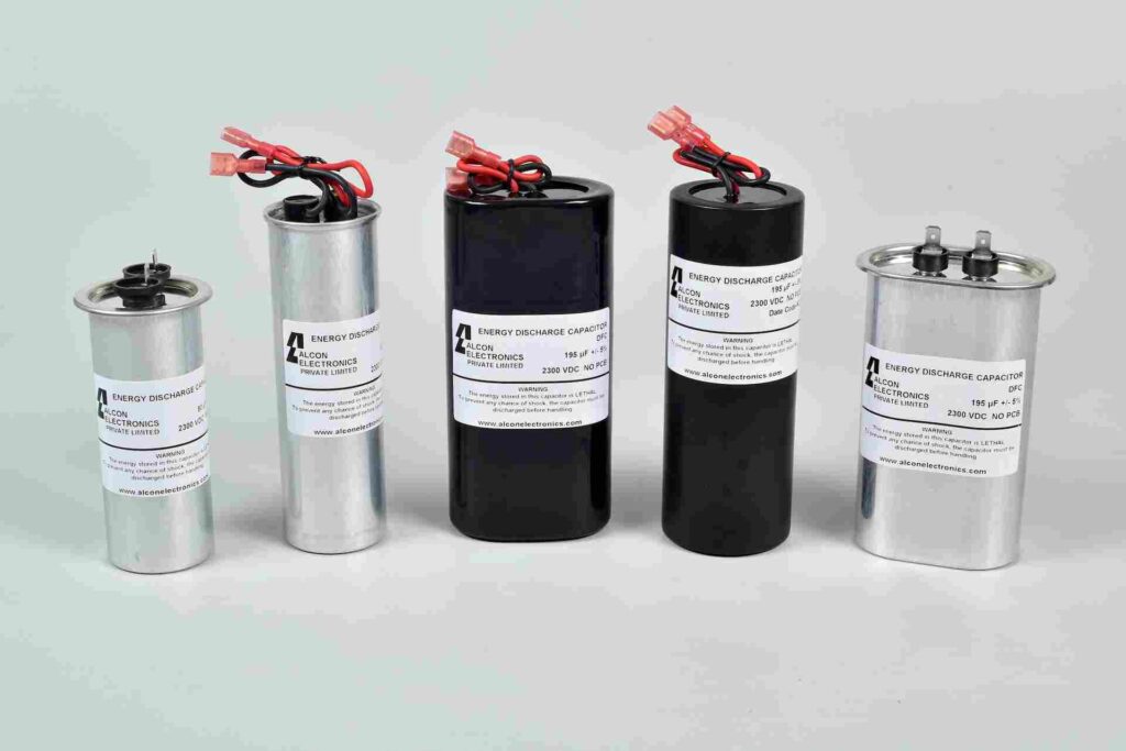
Highlights:-
- High charge / discharge cycles 2000 to 10,000
- Very low ESR
- Very low dissipation factor
- Silicon insulated wire termination and Faston terminations
- Plastic and Aluminum enclosures round and oval
- High energy density
- Monophasic and Biphasic designs
- RoHS compliant
- Flame retardancy UL94-V0
Technical Specification:-
Physical Characteristics
- Dielectric material Polypropylene film
- Electrode material Metallised polypropylene film
- Winding construction Polypropylene film, metallised polypropylene
- Enclosure Performed UL- 94-V0 plastic with thermosetting resin-fill
- Terminals Flexible Silicon insulated UL 94V0 cable.
Electrical Characteristics
- Capacitance range (Cr @ 1 KHz) 32 μF to 195 μF
- Volatge range (Vrdc @ 25°C) 1750 Vdc to 5000 Vdc
- Capacitance tolerance ± 5% or as required
- Tan D @ 100 Hz, 25°C 0.015 max.
- Operating DV/DT 1.275 V/ μS @ 4 pulses / minute, 25°C
- Maximum DV/DT 2.55 V/ μS @ 0.8 Vrdc, 25°C
- Voltage Bleed down (∆ V) 2% after 10 seconds after charged to Vrdc, 25°C
- Normal voltage reversal (Vrev) 10%
- Test Voltage terminal to terminal V t-t 1.1 x Vrdc for 1 minute
- Test Voltage terminal to case V t-c 5000 Vdc 10 Seconds
- Self inductance >1 μH
- Typical operating cycles 2000 to 10,000 cycles
- Operating temperature -20°C To + 65°C
- Storage temperature -40°C To + 65°C
- Altitude Msl to 15000 feet approximate
- Mechanical Shock (IEC 68-2-27) 50 G peak half sinusoidal shock wave, 11 mSec. On 3 axis both directions 3 Shocks / axis
- Humidity IEC 61071 Class F: Max. relative humidity 75% annual means, 85% occasional, 95% 30 days / year, condensation not permitted.
Applications:
Automated External Defibrillators
DFC- Energy Discharge Application In AED
DFC

Highlights
Highlights:-
- High charge / discharge cycles 2000 to 10,000
- Very low ESR
- Very low dissipation factor
- Silicon insulated wire termination and Faston terminations
- Plastic and Aluminum enclosures round and oval
- High energy density
- Monophasic and Biphasic designs
- RoHS compliant
- Flame retardancy UL94-V0
Technical Specification:-
Physical Characteristics
- Dielectric material Polypropylene film
- Electrode material Metallised polypropylene film
- Winding construction Polypropylene film, metallised polypropylene
- Enclosure Performed UL- 94-V0 plastic with thermosetting resin-fill
- Terminals Flexible Silicon insulated UL 94V0 cable.
Electrical Characteristics
- Capacitance range (Cr @ 1 KHz) 32 μF to 195 μF
- Volatge range (Vrdc @ 25°C) 1750 Vdc to 5000 Vdc
- Capacitance tolerance ± 5% or as required
- Tan D @ 100 Hz, 25°C 0.015 max.
- Operating DV/DT 1.275 V/ μS @ 4 pulses / minute, 25°C
- Maximum DV/DT 2.55 V/ μS @ 0.8 Vrdc, 25°C
- Voltage Bleed down (∆ V) 2% after 10 seconds after charged to Vrdc, 25°C
- Normal voltage reversal (Vrev) 10%
- Test Voltage terminal to terminal V t-t 1.1 x Vrdc for 1 minute
- Test Voltage terminal to case V t-c 5000 Vdc 10 Seconds
- Self inductance >1 μH
- Typical operating cycles 2000 to 10,000 cycles
- Operating temperature -20°C To + 65°C
- Storage temperature -40°C To + 65°C
- Altitude Msl to 15000 feet approximate
- Mechanical Shock (IEC 68-2-27) 50 G peak half sinusoidal shock wave, 11 mSec. On 3 axis both directions 3 Shocks / axis
- Humidity IEC 61071 Class F: Max. relative humidity 75% annual means, 85% occasional, 95% 30 days / year, condensation not permitted.
Applications:- Automated External Defibrillators
